
How do you measure beam distance to a kitchen bench?
Identify the light's reference position and the bench plane, measure their axial separation, and avoid using floor distance for a bench geometry calculation.
For a light pointing vertically down at a horizontal kitchen bench, use the distance from the light’s applicable optical reference position to the bench surface, along the beam axis. Do not enter the floor-to-ceiling height unless the floor is the plane you want to describe and the ceiling is also the correct reference position for the light.
The Beam Spread Geometry calculator uses that separation and a full circular beam angle to calculate an ideal circle’s diameter and area. It does not calculate how brightly or evenly the bench is lit. Establishing the measurement points is therefore useful before entering a precise-looking distance.
Where should the distance start and finish?
Start with the manufacturer’s beam-angle information and the reference position used for that geometry. Do not assume that the ceiling, the top of a fitting, the lamp face and the optical origin are interchangeable. A recessed fitting, a projecting light and a pendant can place the light at different positions relative to the ceiling.
Finish at the plane you want to examine: for this task, the bench’s upper surface. The distance is along the beam axis, not a diagonal tape measurement to the edge of the bench. In the supported vertical arrangement, the axis meets the horizontal bench at a right angle.
If the product information does not establish a suitable reference position, ask for clarification. You can explore a clearly stated assumed position, but the resulting geometry inherits that assumption. This ideal point-origin model does not resolve a large emitting surface or verify a real fitting’s distribution.
Can you subtract bench height from light height?
Yes, for the vertical arrangement, if both heights use the same level datum. Let H be the light’s reference height above that datum and b be the bench surface height above it. The axial separation is h = H − b. Both heights must be in the same unit, and h must be positive.
For an artificial example, take H = 2.7 m and b = 0.9 m above the same level floor datum. Then h = 2.7 − 0.9 = 1.8 m. These are invented dimensions, not recommended installation or bench heights.
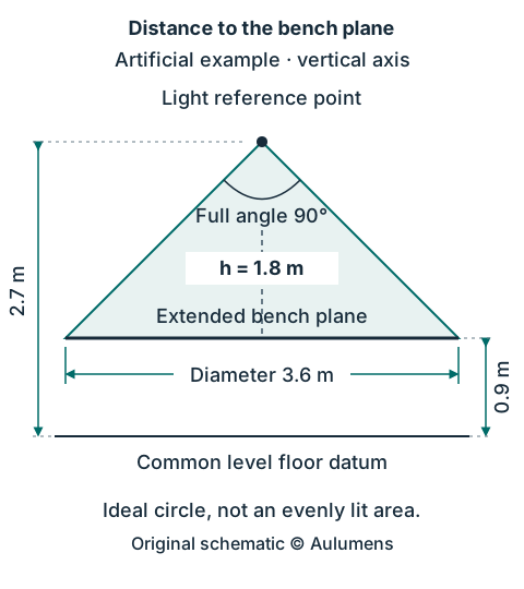
Download the labelled SVG diagram. It contains the same example dimensions and conditions as the diagram above.
What if the two heights were measured from different points?
Do not subtract them until they have a common datum. For example, a light height measured above a raised floor and a bench height measured from a lower floor cannot be combined directly. A sloping floor also needs a consistent level reference; two local floor measurements need not share one horizontal datum.
The relevant quantity is still the axial light-to-plane separation. If you cannot establish it from consistent measurements, record the distance as unresolved rather than treating an assumed ceiling height as a measurement.
What circle does the example produce?
Assume a full angle of 90°, a circular symmetric cone, no obstruction and a horizontal target plane perpendicular to the vertical axis. Confirm that the product’s quoted angle is a full circular angle before applying this model. A half-angle or a pair such as 60° × 90° is a different input.
Bisecting the cone gives a right triangle. Its half-angle is 45°, its adjacent side is h and its opposite side is the radius r. The OpenStax right-triangle relationship, via LibreTexts defines tangent as opposite divided by adjacent. Thus r = h × tan(45°). Since tan(45°) = 1:
- Radius: r = 1.8 × 1 = 1.8 m.
- Diameter: D = 2r = 3.6 m, displayed as 3.60 m.
- Circle area: A = πr² = 3.24π m², approximately 10.1787601976 m², displayed as 10.18 m².
Enter 90 for Full beam angle and 1.8 for Distance along the beam axis, then confirm the geometry only if those conditions apply to your example. Replace the calculator’s preloaded example values. Results update automatically.
What happens if you enter the floor distance instead?
Using 2.7 m would describe a circle at the floor plane in this example, rather than at the bench plane:
| Plane being described | Axial distance | Diameter | Unrounded area | Displayed area |
|---|---|---|---|---|
| Bench plane | 1.8 m | 3.60 m | 3.24π m² | 10.18 m² |
| Floor plane | 2.7 m | 5.40 m | 7.29π m² | 22.90 m² |
The floor distance is 1.5 times the bench distance, so the ideal diameter is 1.5 times as large and the area is 1.5² = 2.25 times as large. That is a change in geometry, not evidence about illuminance at either surface.
The calculator displays diameter and area to two decimal places. Keep the unrounded radius when calculating area, then round the final value; do not derive a new area from a previously rounded output. The mathematical relationship is sourced above; the dimensions, numerical example and SVG are original illustrations, not copied product data or source artwork.
The linked OpenStax section is provided by Mathematics LibreTexts under CC BY 4.0. Its tangent relationship is explained here in the context of a beam cross-section; the source’s figures and worked examples are not reproduced.
When does this measurement method stop being enough?
A tilted light does not meet a horizontal bench at a right angle. A vertical height difference alone is then not the axial distance, and entering a diagonal distance does not make the calculator’s perpendicular-plane model describe the tilted intersection. Asymmetric beams and obstructions also fall outside its circular, unobstructed model.
Even within the ideal geometry, the angle-defined circle does not establish a useful lighting boundary. It gives no lux values, uniformity, shadows or glare assessment, and no recommended light spacing or number of fittings. Use the measured separation to understand the geometric input; assess actual task lighting with the relevant product photometry and project conditions.